
Description
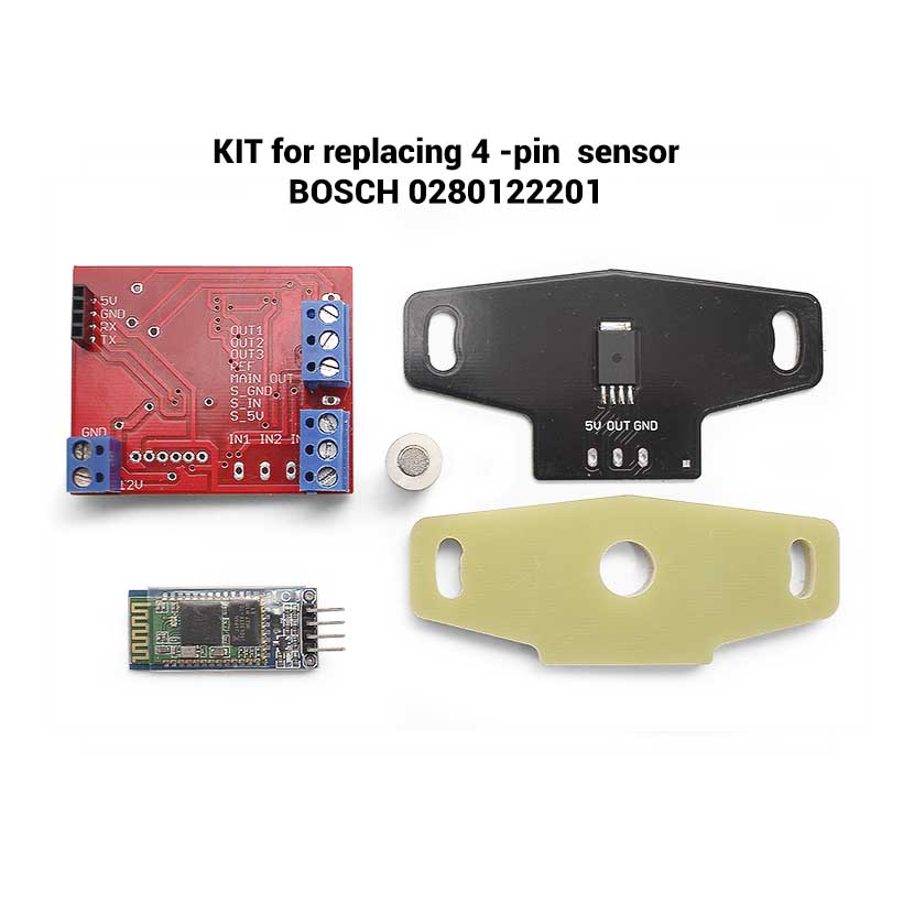
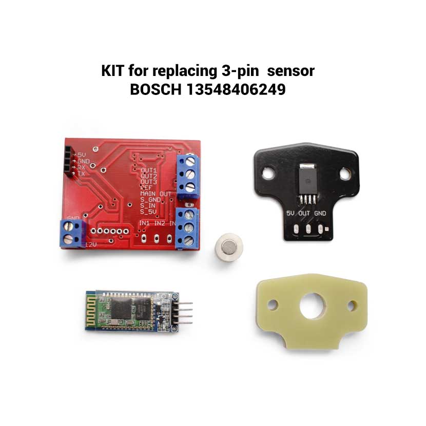
This kit is intended to replace
genuine Throttle Position Sensors (TPS) Bosch 0280122201 and 13548406249 on BMW series:
- R1150
- R1100
- R1200
- R850
- K1
- K100
- K1100
Also we have universal sensor which could be used for replacing any genuine TPS on any motorcycle or vehicle – just write to us in the comments or on e-mail and we will help you with this.
Sooner or later, the owners of BMW motorcycles of the above series
face the following malfunctions:
-the engine periodically stalls at speeds close to idle,
or the idle speed is not stable
-there are periodic jerks or dips at a certain position of the throttle
-it is not possible to drive at low speed at low revs,
the motorcycle jerks or stalls and you have to rev and burn the clutch
To eliminate these malfunctions, the first step is to check
the condition of the spark plugs and the ignition system as a whole, as well as the fuel supply system.
Provided that the ignition and fuel supply systems are in good working condition, the only reason for the above problems
is the throttle position sensor, or rather the wear of its resistive tracks.
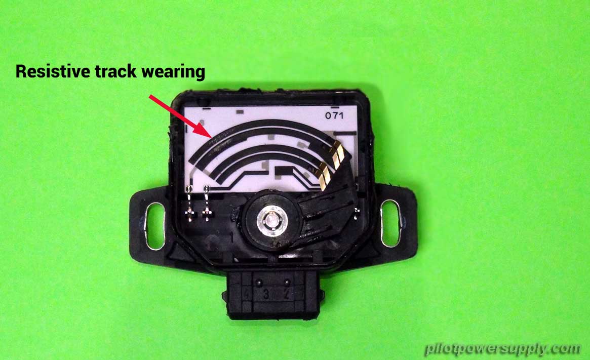
To check the performance of the 4 -pin BMW TPS sensor, it is necessary
with the ignition turned on, measure with a multimeter or oscilloscope smooth increase in voltage on contacts 1 and 3 relative to groundwhen smoothly opening the throttle from zero to maximum.
If there are sharp dips or surges during the measurement, then the TPS has wear, as in the picture above, and needs to be replaced.
Unlike Bosch 0280122201 and 13548406249
Pilot TPS sensor is absolutely not a subject to physical wear.
This is explained by the fact that the determination of the angular position of the throttle occurs in a contactless way.
The principle of operation of the Pilot TPS Converter is based on the measurement of the angular position of the magnetic field,
created by a magnet that is mounted on the throttle’s shaft.
Special chips and processor of the Pilot TPS Converter board
convert the measured value of the throttle angle into electrical signals, which characteristics are absolutely identical to the signals of the genuine Bosch 0280122201 and 13548406249.
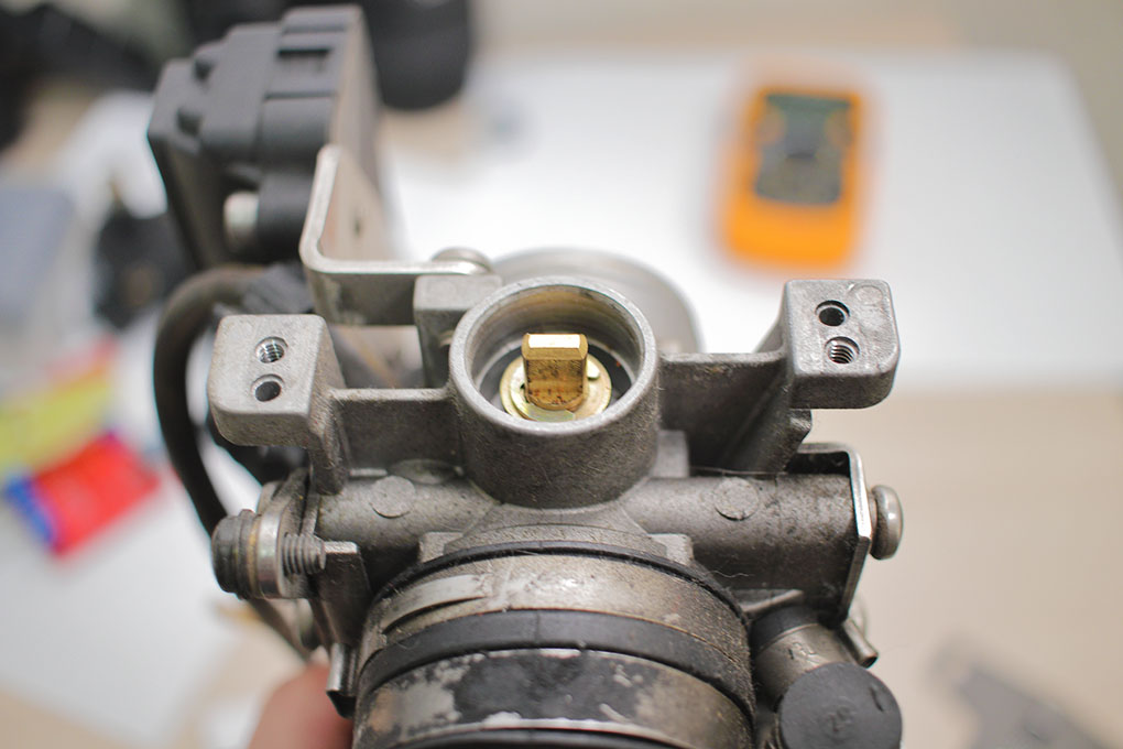
First of all, you need to remove the old sensor from the throttle
Now you can install the bushing with magnet.
In this case, a little automotive sealant must first be applied to the throttle axis.
After hardening, the sealant will reliably fix the bushing on the axle (prevent it from turning))
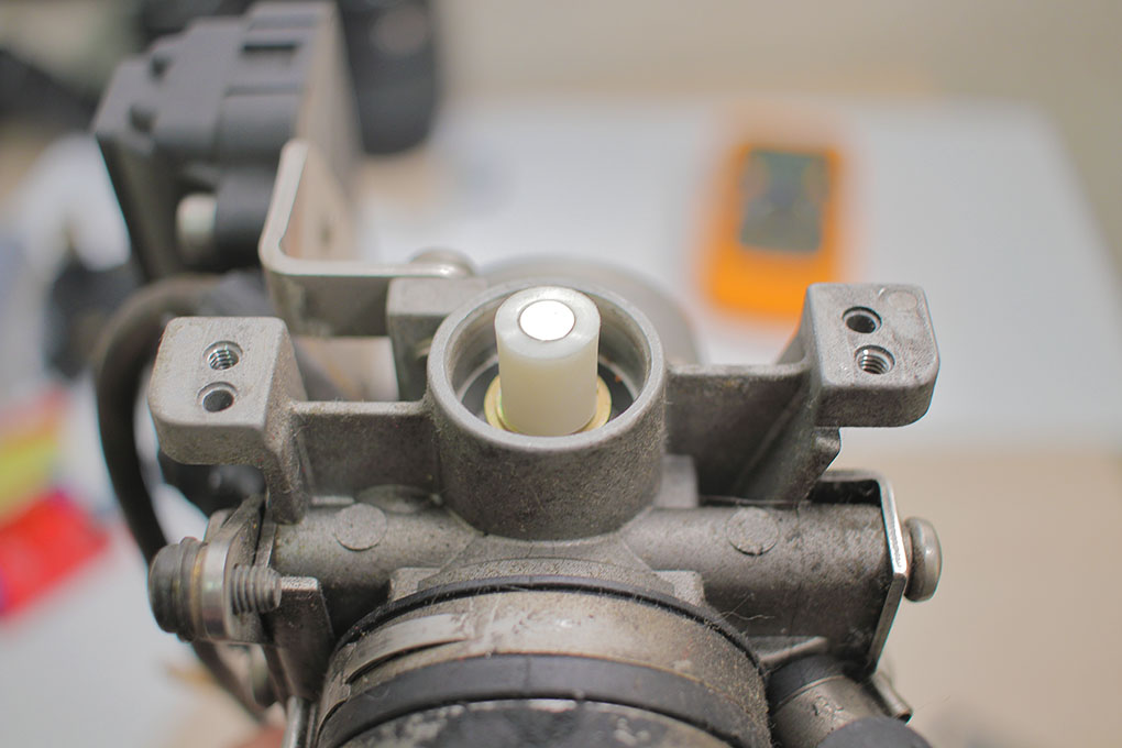
Next, install a set of spacers
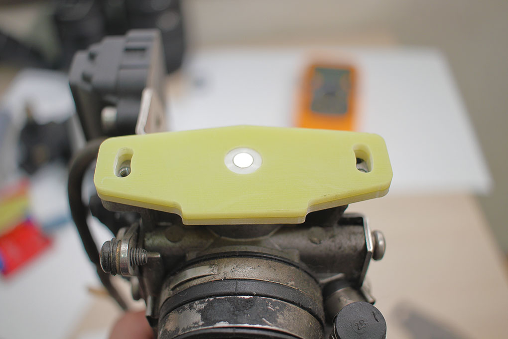
Install the sensor from above and fix it with screws.
In this case, before the final tightening of the fastening, the sensor must be turned fully counterclockwise or clockwise (for sensors with cutouts).
This rotation will provide accurate centering of the sensor relative to the axis.
As a result, we should get this design.
The photo above does not show the wiring.
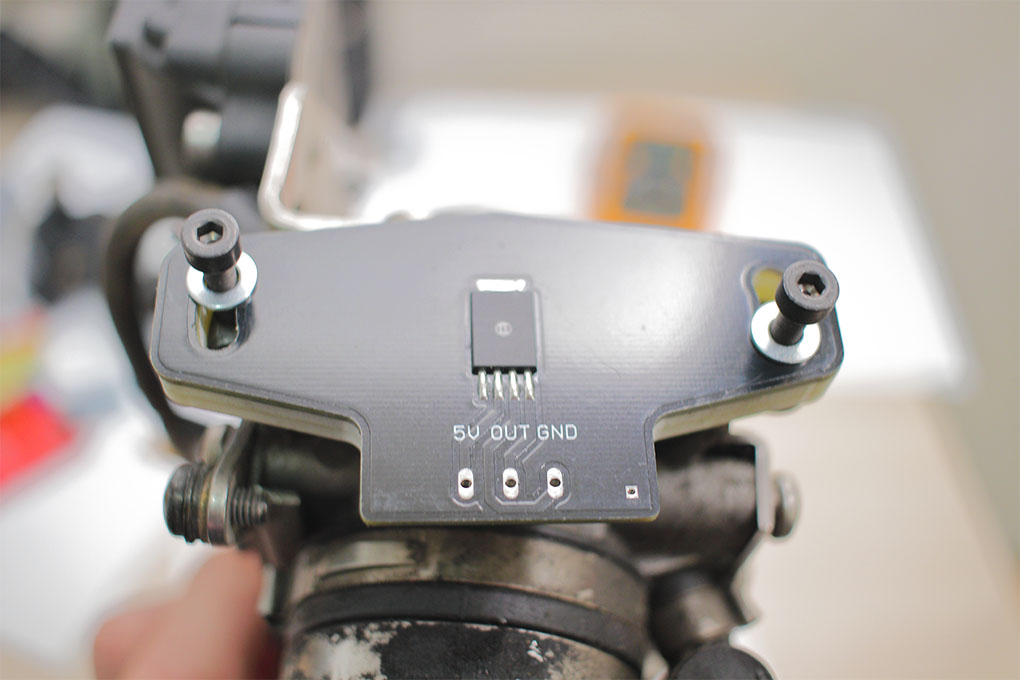
Of course, before installing the sensor, you need to solder a wiring.
After that, it is necessary to cover the soldering points, the wiring on the back of the sensor
and the sensing element of the sensor with conventional automotive sealant.
For application, it is most convenient to use a medical syringe.
The sensor’s wiring must be connected according to the following diagram:
Attention! The colors of the wires are indicative and may differ on different motorcycles.

For standard 3-pin sensors like Bosch 13548406249, output # 2 of the converter does not need to be connected anywhere.
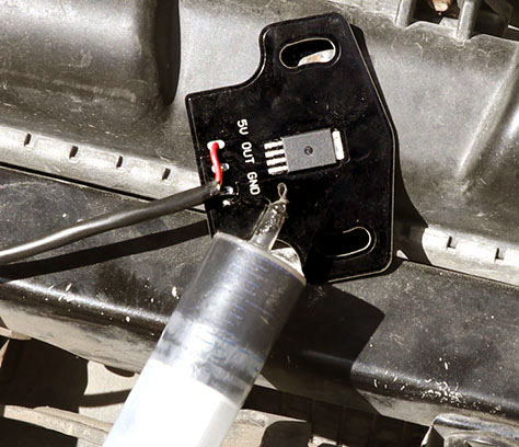
Pinout of the main red board and recommendations for connection
S_GND – contactless sensor signal ground, connects the contactless sensor ‘sGND contact
S_IN – contactless sensor signal input, connects to the OUT contact of the contactless sensor
S_5V– power output for the contactless sensor, connects to the 5V contact of the contactless sensor12V-main board power supply 12V, must be connected to the ignition switch.
When the ignition is turned on, the power should appear, when the ignition is turned off, it should disappear.
It is recommended to protect this circuit with a 3-5A fuse, which should be located as close as possible to the connection point of the main wiring of the motorcycle.
GND– Supply ground.
Attention! There are two options for connecting the converter’s ground:
1. The ground is connected directly to the negative lead of the battery or to the point where all the grounds are connected together on the terminal block. This is the main connection option and I highly recommend to use this option.2. The mass can be connected to the ground signal wire of the standard TPS (as shown on the diagrams). But on some motorcycles this leads to problems due to signal interference. Therefore, it is recommended to connect the mass according to the first option..
Ref-reference voltage input, usually 5V. This input is connected to the reference voltage wire of the genuine TPS wiring.Out3- output 1 of track #1 – connects to the wiring of the genuine TPS.
In the case of a 4-pin TPS sensor, this is the output of the first track, the voltage on which varies in the range from 0 to 25 degrees of throttle opening.
In the case if genuine TPS is a 3-pin sensor,at this output, the voltage will change in the range of angles from 0 to 90 degrees of throttle opening.Out2-output 2 of track #2 – connects to the wiring of the genuine TPS.
In the case of a 4-pin TPS sensor, this is the output of the second track, the voltage on which changes in the range from 15 to 90 degrees of opening the throttle.
In the case if genuine TPS is a 3-pin sensor, this output does not need to be connected anywhere.In1-input of an oxygen sensor’s signal – will be used for fine tuning the mixture according to the oxygen sensor readings. Also this input can be used to diagnose the oxygen sensor.
How to determine the pinout of a genuine TPS sensor and compliance with the wiring diagram?
For 3-pin TPS sensors everything is very simple – with the ignition turned on, use a voltmeter to find the ground (there is usually 0V), the reference voltage (4.8-5v regardless of the throttle position) and the output signal which changes from 0.2 to 4.8v in proportion to the throttle opening.
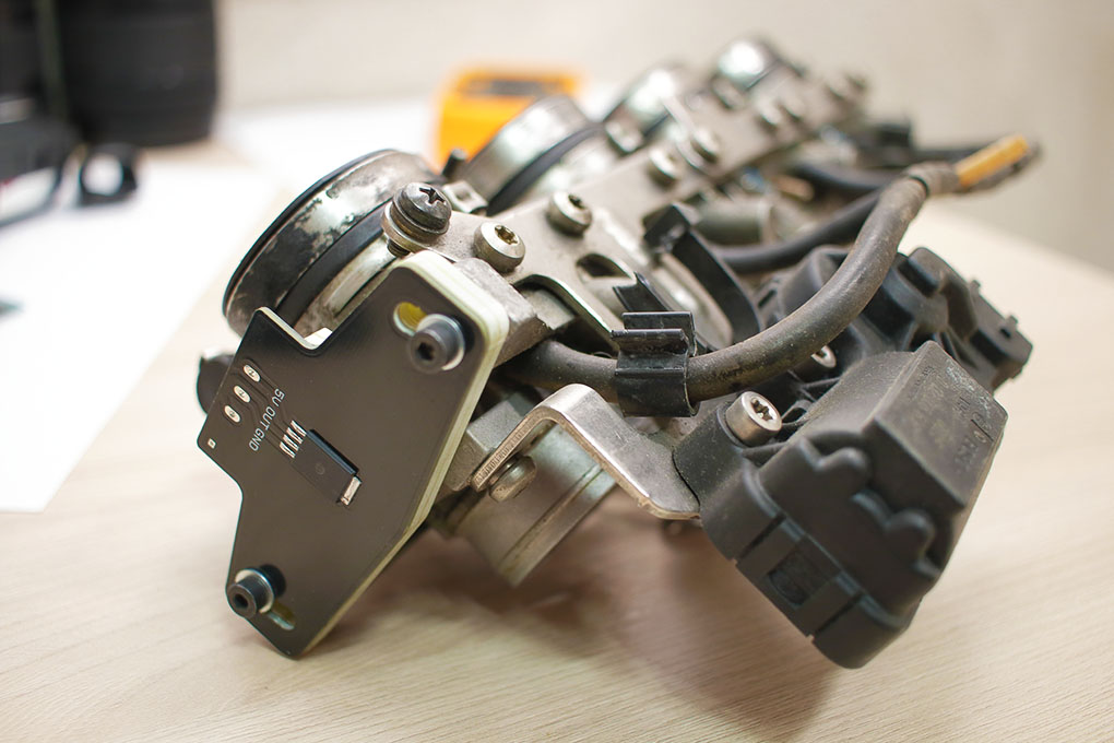
On 4-pin sensors like this
contact numbers are marked with digits on the body of the sensor and have the following pinout:
1-out of the track #1
2-reference voltage 5V
3-output of the track #2
4-signal ground (usually not used when connecting anew contactless sensor, since the converter ground must be connected to the negative lead of the battery)
Calibration and adjustment of the contactless TPS on example of the K1200RS throttle
Before the initial calibration of the magnet position, the throttle must be fully closed.
To do this, it is necessary to disconnect the connector from the idle regulator and apply voltage to the corresponding contacts from a 9v battery.
In this case, the idle regulator’s rod should be fully retracted into the body, and the throttle lever should rest on the stop.
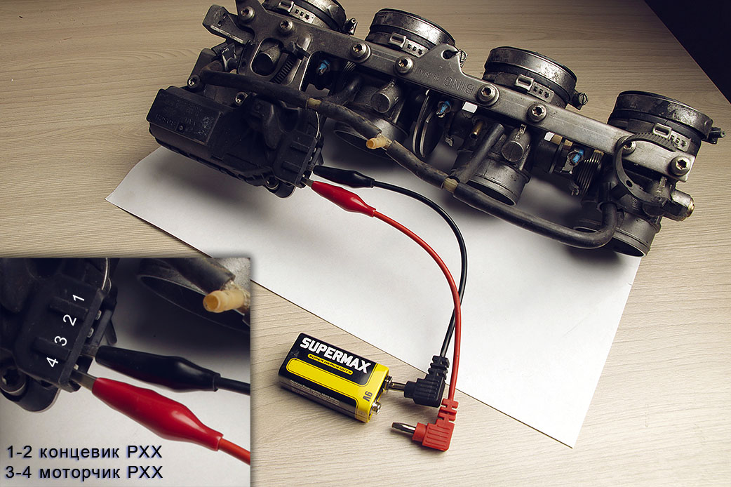
If, when connecting the battery, the rod moves out of the body, then you just need to change the polarity.
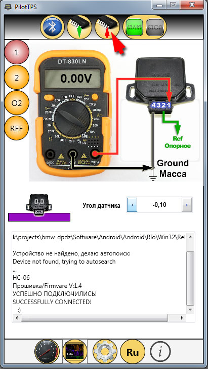
To configure and calibrate new TPS, you need to install the application on your smartphone or laptop.
New beta -enhanced connection via bluetooth
After that, you need to turn on the ignition, and the LED of the bluetooth module will start blinking.

Next, you need to search for new bluetooth devices on your smartphone or laptop.
A new HC-06 or Pilot TPS device should appear in the list – add it to the system.
Standard pairing password: 1234
Now you need to launch applications and press the bluetooth connection button.
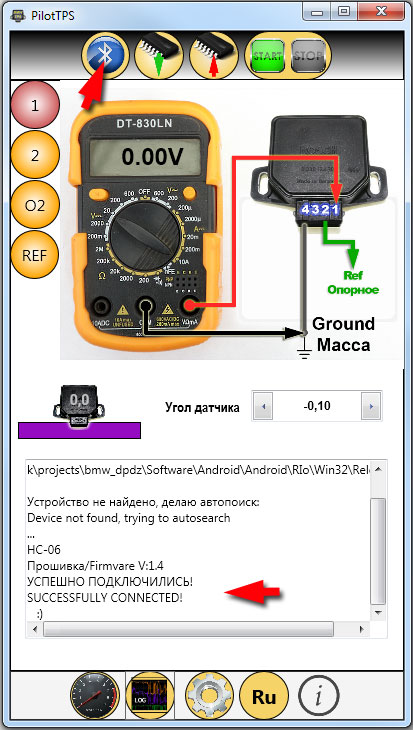
After the application connects to the device, you will see a corresponding message in the log, and the LED on the bluetooth module will light up constantly.
For initial calibration, click on the sensor image.

In the menu that appears, first of all, you must select the type of emulated sensor – 4pin or 3 pin
After that, it is necessary to turn off and turn on the ignition again (with an exposure time of 5-10 seconds in the off state), and reconnect to the converter via bluetooth.
Open the calibration menu and press the calibration button with the throttle fully closed.
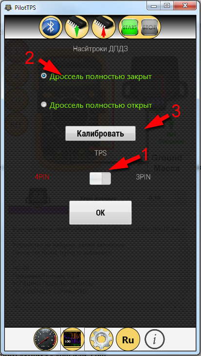
Within 10-15 seconds, the sensor will determine and remember the position of the magnet on the axis, after which this position will be taken as the point of the fully closed throttle.
Note:
The calibration is saved in non-volatile memory, disconnecting the battery cannot reset this calibration. Recalibration may only be required if the sensor will be removed from the throttle for maintenance or by other reason.
After calibration of the initial position is done, you need to connect the connector to the idle regulator, press the start / stop button in the application and try to start the engine.
The virtual rotation of the sensor, or rather its output voltage, can be changed by clicking on the arrows.

To rough tune the 4 pin sensors, it is necessary to disconnect oxygen sensor so that the ECU does not change the mixture.
At this stage, your task is to achieve the most stable engine idling.
The general recommendation for 4 pin sensors is to change the virtual angle to minus until the engine starts to lose speed (or change the sound of operation), then icrease virtual angle to plus until the engine starts to lose speed or the sound of its operation starts to change. Having memorized these two values, choose the average between them.
For 3-pin sensors, you just need to set the output voltage according to the manufacturer’s recommendation controlling it with a multimeter. In the process, slightly adjust virtual position, according to the sound of the engine and the reaction to opening the throttle.
Note:
The voltages displayed by the program are conditional and are calculated for a 5V reference voltage. In fact, the reference voltage on your motorcycle may be slightly more or less, therefore, it is recommended to control the specific value for a 3-Pin sensor with a real multimeter directly at the converter’s output.
At the end of the adjustment, before turning off the ignition, it is imperative to save the value of the virtual angle of the sensor to non-volatile memory.
To do this, click on the IC with a red arrow.
After that, you can reconnect the oxygen sensor to the ECU.
At this, the rough adjustment can be considered complete.
Fine tuning of the sensor by using an oxygen sensor
To fine-tune the position of 4-pin sensors(and corresponding mixture), we can use the oxygen sensor.
Before such adjustment, it is recommended to reset mixture adaptations of ECU with using a scanner or simply by disconnecting the battery for a short time.
To carry out fine tuning, the Oxygen Sensor signal wire must be disconnected from the ECU and connected to the corresponding input of the converter board.
(It is recommended to install some toggle switch or a latching button).
Attention! The colors of the wires are indicative and may differ on different motorcycles.
Disconnecting the Oxygen Sensor signal from the ECU is necessary so that the ECU does not make adjustments to the mixture.
Color pinout of Bosch zirconium Oxygen Sensors:
Black wire – signal (we need it for tuning)
Gray wire – signal ground.
Two white wires – heater.
Now we need to start the engine and warm it up to operating temperature.
Rev up and hold 3000-4000 rpm
After that, observing the readings of the Oxygen Sensor signal, we need to achieve a value from 0.45 to 0.65V by virtual rotation of the sensor at 3000-4000 rpm.
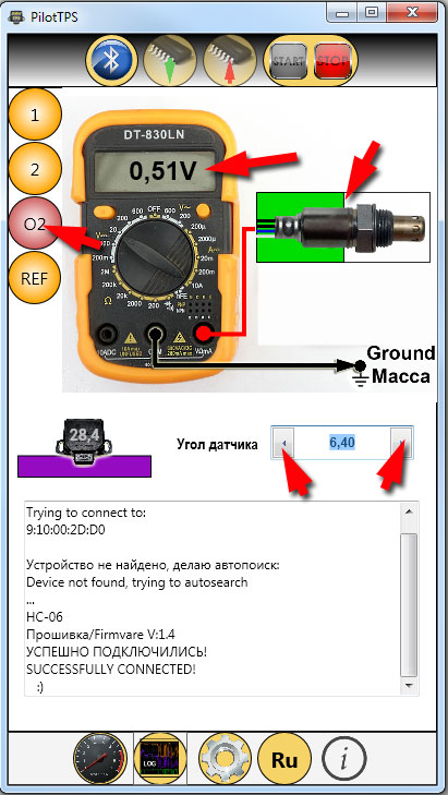
If it is impossible to accurately achieve the readings of 0.45-0.65v, then we proceed as follows:
We rotate the sensor virtually towards lean mixture until the Oxygen Sensor signal becomes equal to 0V (lean mixture).
Now we begin to gradually rotate the sensor in the direction of enrichment, and here our task is to catch precisely the transition of the mixture from lean to rich, i.e. Oxygen Sensor signal
will jump from 0v to 0.8-0.9v – this will be considered the optimal setting.
After that, you need to save the virtual position of the sensor to the memory of the converter.
And reconnect the Oxygen Sensor signal to the ECU (with a toggle switch, or restore the wiring connection).
You dont need to disconnect Oxygen Sensor signal wire from converter and it can be used to monitor the Oxygen Sensor signal and to watch how the ECU adjusts mixture.
On this, the installation can be considered complete and it remains only to check the whole thing in motion.
Well, if you still have any questions or doubts – write in the comments 🙂
P.S. we can develop similar sensors for other brands of cars and motorcycles. Suggestions about this, please contact support(dog) PilotPowersupply.com


Максим –
Добрый день. Хотел бы купить Contactless TPS for BMW motorcycles как это можно сделать? Могу ли оплатить русской картой и есть ли доставка в Россию?