Description
This Pilot VAF to MAF converter
allows you to convert an existing Volume Air Flow Meter to a Mass Airflow Meter.
Why convert from the existing Volume Air Flow arrangement to a Mass Air Flow setup?
Anyone whose ever looked at the OEM Vane/ Volume Air Flow (VAF) sensor knows that it is a restrictive device by its very design.
The calibration of this sensor is VOLUME meaning that the sensor is largely temperature-insensitive (note however that a mass conversion occurs in PCM and IAT plays a big role in that). The mass of the ingested air is obtained from calibration tables as well as an IAT (Intake Air Temperature) sensor in the VAF and barometric pressure sensor in the PCM.
If the VAF has one redeeming quality it is that it is very sensitive to small airflow changes at low levels of airflow. Thus, at idle, the sensor very effectively tells the PCM of minor changes in airflow which results in a nice smooth idle and very efficient fuel metering.
The problem arises from the way the device measures airflow. Since the core or flap moves backward against a calibrated spring, a not-inconsiderable force is required to hold the core open at high-levels of airflow. This force is provided by the incoming air. In return, the airflow loses pressure and velocity which reduces the amount of air ingested by the engine.
In contrast, a Mass Air Flow (MAF) sensor from practically any other engine is largely a straight through affair. This device uses two resistive elements that sample only a portion of the incoming air. A temperature differential is kept between these two wires. As air flows over them, it tends to cool them. The electronics measures how much additional current is required to maintain the temperature and translates this to a voltage ranging from 0.1V to about 4.5V. Since only a portion of the air is sampled, the MAF is a very-much less restrictive measuring device.
The VAF meter also has a problem with а damaging resistive track inside it.
Restrictive VAF or non-restrictive MAF – what is your choice ?
Restrictive VAF Snesor


Typicaly the VAF Sensors also have a problem with damaging potentiometer track because they are old, which gives poor idle , engine stall etc.

Or look at the new style non-restrictive MAF sensor


The Converter
The brains of the conversion is a RISC microcontroller clocked at 12.8-MHz. This device reads the MAF sensor and calculates the equivalent volume of air, scaled to the OEM VAF sensor’s characteristic from a special table of conversion. This calculated volume is then used to create a voltage signal which is sent to the PCM. The system is designed such that the PCM thinks the airflow is being measured by a VAF, necessitating no changes be made to the PCM itself.
The converter supports two operating modes:
1)Simple mode for VAF meters with reference voltage in range of 0-5V
2)Universal mode for VAF meters with reference voltage in range of 0-12V on LE-jetronic and other old style engine management systems.
Also this version of the converter has an additional precision DAC for best perfomance.
The converter has an upgradable firmware future, so if we’ll add some new features to software or firmware you can download and make upgrade for free very easy.
The IAT Sensor
The IAT (intake air temperature sensor) is located within the VAF. Once the VAF is removed from the car, so too is the IAT sensor. This clearly presents a problem since the PCM requires the IAT (along with the volume & barometric pressure) to calculate the mass of incoming air from the volume reading. The better way to resolve this problem is to remove original IAT sensor form VAF and install it in intake tube. And connect corresponding signal to IAT input of the converter.
Also you can connect engine coolant tempertaure sensor (ECT) and aplly corrections based on IAT and ECT readings
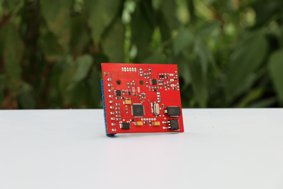
Bottom view

Examples of VAF to MAF conversion
For example let’s install Pilot VAF/MAf and MAF Bosch 0 280 217 533(BMW e38 M62TU) on BMW e34 m30b30 engine, all photos and conversion table made by igor90935 also here is he’s project on russian
I’ll try to translate it to you, and explain how to install it. Also you can find a lot of projects and conversion tables on russian part of our forum
Also you can find some projects on english part of our forum


On last photo he install the Pilot VAF to MAF converter in special case and put it near ECU 🙂
and here is he’s conversion tables
first
and
second
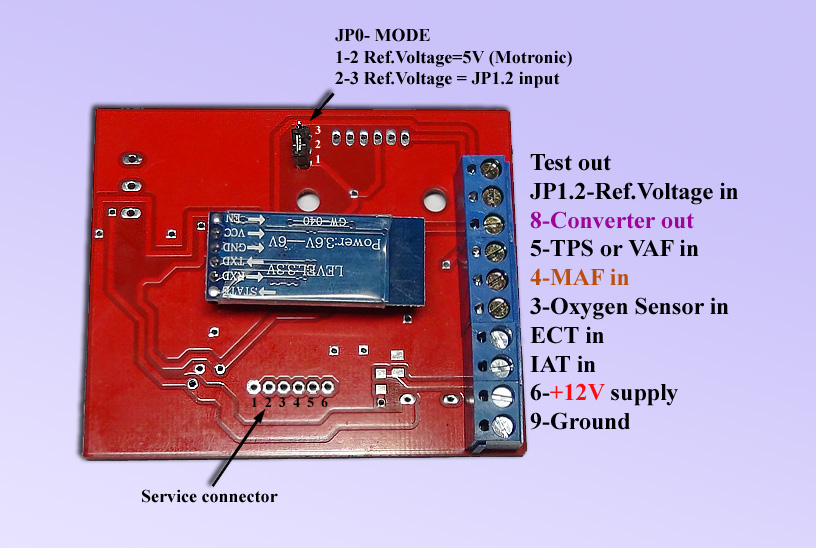
Pilot VAF to MAF converter pinout
Board V2

Board V1

in bluetooth version there is no USB connector.
Helpful links:
Forum about the converter
Installation & Tuning
Mainboard pinout
Version 2
Version 1
in bluetooth version there is no USB connector.
Installation and Tuning
For tuning the conversion table you’ll need to connect converter to the PC via bluetooth ( password 1234) and use Pilot Configurator Software. This Software has build-in dashboard , table editor, Data Logger, Compare Tables util and other feauteres.
1. Measure the output and the reference voltage of VAF at the engine idle. Recalculate the output voltage of the VAF to the ADC / DAC (digital signal converter) readings of converter according to the formula
ADC = (Uoutput / Ureference) * 255
In fuel injection systems, where the reference voltage is not applied to the VAF((or exits from the VAF ), the output signal is typically in the 0-5V range , and a 5V is taken as Ureference.
Typically BMW Motronic VAF uses 5V reference voltage, BMW LE-Jetronic VAF poduces reference voltage to the ecu typically 6-10V, Mazda EFI 5V or 6-10V in different versions etc. If you need help with this measuring – ask on forum.
2.Fill in the conversion table with the resulting ADC value or use 1:1Table from menu.
For 4-cylinder engines on the tab “Conversion table” set the “MAF smoothing factor» = 5
Save table to the file and to the converter, don’t forget to give supply voltage to the converter, before writing table to it.
Table Graph → 1:1
For 4-cylinder engines on the tab “Conversion table” set the “MAF smoothing factor» = 5
Conversion Table → File→Save
Converter→Write table to converter( don’t forget to give supply voltage to the converter before it )
For example we have measured VAF output at idle =0.8V and reference voltage=5V for BMW e34 m30b30 BOSCH Motronic,
so ADC =(0.8/5)*255=40.8 ~41
Now let’s null and fill in all table cells with this value, and after that save it to the file and to the converter.

3.Warm up the engine to operating temperature with standard VAF.
After that delete VAF and install MAF + Converter following one of the schematics bellow.
If standard VAF absent or broken, you can install MAF +Converter and warmup the engine by using correction function of Pilot Configurator and manually adjusting RPM and mixture
Installation schematic for VAF with output voltage in 0-5V range and reference voltage 5v ( or without reference voltage) like BMW Motronic
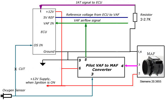
Install jumper JP1 to 1-2 position ( see converter pinout figure). The VAF’s incoming air temperature sensor must be replaced by a constant resistor. The resistance of this resistor should be the same as the resistance of the intake air temperature sensor at 20 °C , for most injection systems suitable resistor 2-2.7KOhm.
Installation schematic for VAF with output voltage in 0-12V range and reference voltage 6-12v ( produced by VAF) like BMW LE-Jetronic or old Mazda EFI

Install jumper JP1 to 2-3 position ( see converter pinout figure).
Disconnect the VAF and measure the resistance between the ground and the reference voltage (R1-2) and the resistance between the reference and supply voltages R2-3. Collect the resistive voltage divider by using resistors with nominal power not less than 0.5W R1 = R1-2 and R2 = R2-3. Connect the divider according to the scheme above.
For both schemes
The Oxygen Sensor(OS) output signal is the composition of the mixture- must be connected to the #3 input of the converter, and the need to temporarily disable this signal from the ECU. Turning off the OS signal from the ECU need to ECU did not make any mixture corrections. After you tune the conversion table do not forget to restore the OS signal to the ECU.
4. Turn on the ignition.
In the Pilot Configurator, select the appropriate COM port that is connected to the converter. After that, click the “DashBoard” tab.
If you have made the installation by using the second scheme( for VAF in 0-12 range like Jetronic), the configurator will generate an error reading table because the converter will be de-energized prior to the engine start. In this case, open the prepared table in paragraph 2 from file.
5.Turn on the starter and quickly press the arrow keys ↑ or ↓ a few times, in this case the dashboard will startup, and you’ll see a red square running on a graph – the current modeline point( an accordance of MAF and Converter’s output).
6. Use the arrow keys ↑ and ↓ until you get a stable operation of the engine at idle, if necessary, keep engine running with these keys. Likewise, you can warm up the engine, if standard VAF is damaged or missing.
7. Upon reaching the engine operating temperature check “AUTO” correction in the dashboard tab.
In this case Pilot Configurator software will automatically calculate and set the optimum window of correction for a given point of the regime.
Also it will try to autotune AFR to O2ref. value.
8. Also you can tune mixture maually by uncheking Autocorrection box, then wait for a 1-2 seconds for the installation of the window of correction.
Use the arrow keys ↑ and ↓(or correction), and the indications of the O2 (oxygen sensor signal) until the optimal composition of the mixture, in this case the color of the O2 will be green or yellow. The blue color of O2 indicates lean mixture, red-the rich Mixture.
In some cases, you can not just get to the yellow-green range, then you must make the mixture lean(blue) and slowly enrich the mixture to a transition in the rich area (red). The correction value at the transition point of a mixture of rich and lean is optimal.
After you have tune the mixture in current point, press “Enter” key on the keyboard, in this case the correction will be applied to the appropriate section of the table and new table will be loaded into the converter’s RAM memory.
9. Add a little accelerator pedal and tune the mixture into the new regime point, etc. Do not forget to press the Enter after tuning each point in manual mode. In autocorrection mode dont press any keys. When you will tune some points on road in motion you may need help mate.
10. After you tune the entire table, save it to the file and to the converter.
If you accidentally turn off the ignition, or a program failure has occurred, you can use file RAM.tab This file contains the backup table that had been written into the converter at the last press Enter.
11. Check the reaction to the quick opening of the throttle. With the quick opening of the throttle there should not be a strong lag. If there is strong lag, then for the four-cylinder engines need to reduce a bit the MAF smoothing ( set higher value , 100- minimum smoothing 1-maximum smoothing). You can also try to adjust the acceleration enrichment parameters at the “conversion table” tab.
12. Reconnect the signal wire of the oxygen sensor to the ECU.
Congratulations, the installation is complete!
Management and navigation on the charts
Scaling
Hold the left mouse button + drag left and down to zoom. To return to the original scale – left mouse button + drag to the right and upward
Scroll
Hold the right mouse button and drag the graph with the mouse.
Editing points
All significant points on the graphs can be dragged with the mouse, with a table containing all the changes on the fly.
Double click
If the point is outside the visible area of the graph, make a double left-click, and it appears at the cursor position. Then just tighten where necessary.
The context menu of graphs (right mouse button)
1. Turns off / on the points
2. Turns off / on the tips (not all charts)
3. Disable / enable the corresponding curves
Main board pinout

Typical connection diagram of the contactless version

Wiring recommendations
Power Ground
The converter’s power ground must be connected to the signal ground of the airflowmeter.
This will exclude voltage errors, current loops and noise pickups.
Before connection by using a multimeter make sure that the ground of the flowmeter is connected on the chassis ground and has a minimum resistance of not more than a few ohms.
If it’s not so, then connect the converter’s power ground directly to the ECU power ground.
12V power supply
During tuning connect converter power supply directly to the car battery through the 1-5A fuse. This will prevent loss of communication with the converter and loss of data from the tables during tuning in case of the engine stop and will significantly simplify the tuning process. After tuning is completed, connect the converter power supply to one of the circuits powered from the ignition switch. With the ignition switched on the power must be supplied to the converter, and with it switched off – not supplied.
REF reference voltage
In the Jetronic systems with a 6 V-12 V flow meter reference voltage, which depends on the temperature of the incoming air (IAT makes the correction of ref voltage), as well as in the Motronic 1.0 systems with a flow meter reference voltage higher than 5 V, this voltage must be necessarily fed to the REF pin of the converter board, as indicated in the standard connection diagram.
In newer Motronic systems and the like, the reference voltage of the flowmeter is usually 5V and does not change depending on the incoming air temperature (there is a separate sensor and a separate IAT signal).
In such systems the reference voltage may not be connected to the converter board, but a jumper between the contacts REF and S_5V must be installed instead. In this case the internal 5V voltage of the converter board will be used as the reference voltage.
Oxygen Sensor
Connect signal of the oxygen sensor permanently to the converter.
If the OEM oxygen sensor is missing on the car, you will need to install it.
Fine tuning is impossible without oxygen sensor!
It is obligatory to disconnect oxygen sensor signal from ECU during tuning.
Otherwise ECU will make its mixture corrections and you will not be able to tune mixture.
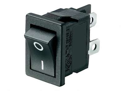
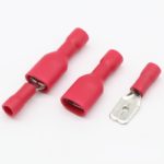
To temporarily disconnect oxygen sensor from ECU, it is necessary to install a microswitch in the signal wire gap or terminals of male-female type to break the wire.
Installing contactless sensor in the airflowmeter
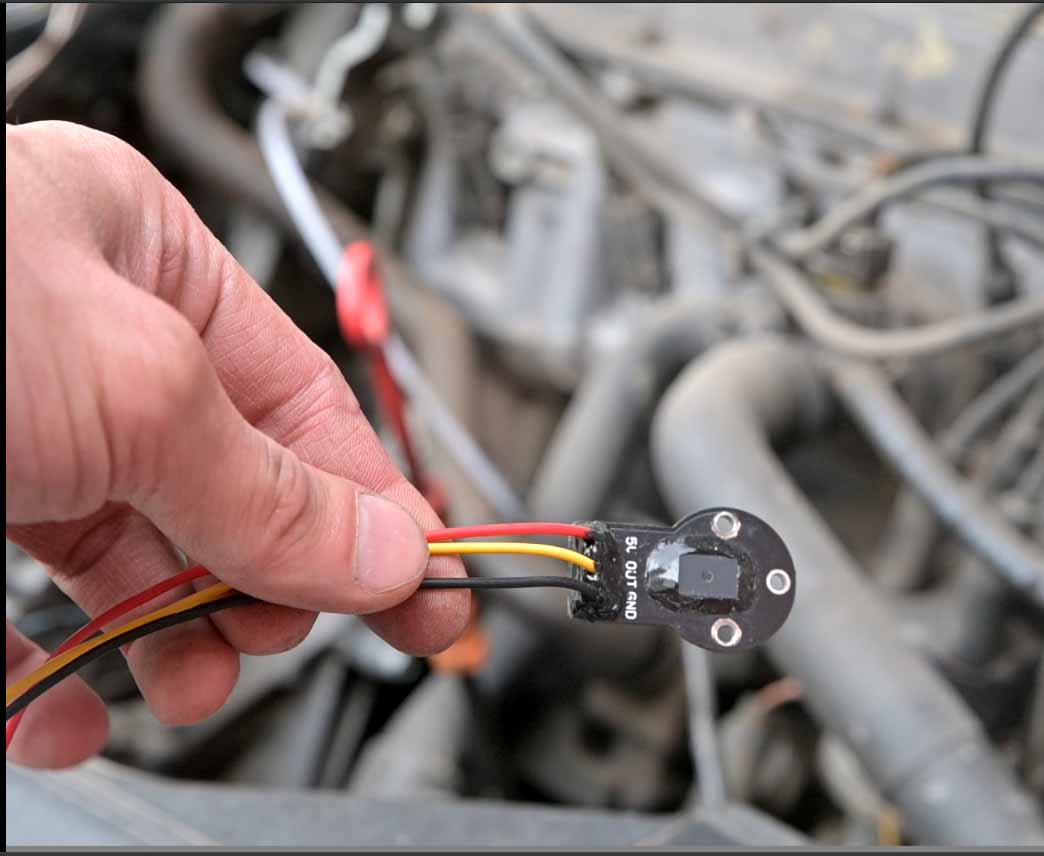
Preparing the contactless sensor
It is necessary to solder wires 30-40 cm long to the sensor.
After that, it is necessary to cover its pins and the places where the wires enter the board with an acid-free sealant or car varnish to protect against oxidation.

Soldering the wiring must be carried out from the side of their insertion into the board (from the side of the inscriptions 5v, out, gnd). When soldering, the sensor must be placed on some flat plywood or plank and pressed tightly against it. This is necessary so that the solder does not flow out to the reverse side and does not violate the plane of the sensor mounting (protrusions of solder or wires on the reverse side).

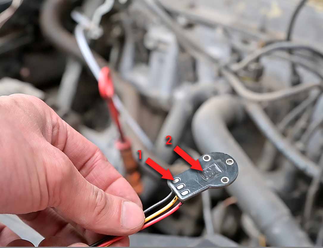
Arrow 1 indicates the contacts that should be in the same plane with the sensor board. There should be no protrusion of solder and wires in these places. Arrow 2 – shows the sealant cover of the sensor on the reverse side. Excess sealant immediately after application is removed with a clerical knife blade (like a spatula). Thus, we provide a plane on the back of the sensor.
Airflowmeter preparation
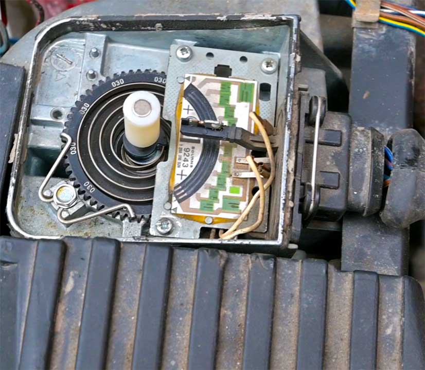
Toyota and Mazda airflowmeters
When installing the sensor on Toyota or Mazda flowmeters, it is necessary first of all to solve the problem of controlling the fuel pump relay.
In these flow meters, the fuel pump is controlled by contacts in the flow meter (indicated by the arrow number 2 in the photo below), which in the event of a frontal accident opens when the engine stalls and ensure that the fuel pump is turned off to prevent fire.
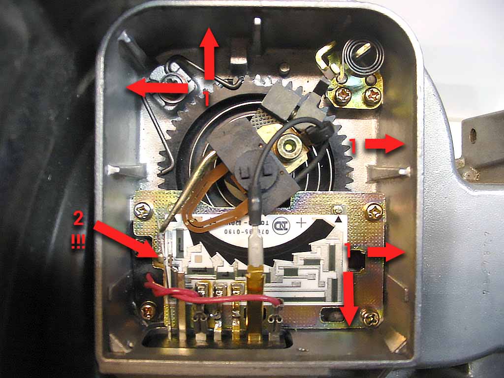
1- possible locations for the contactless sensor wiring output (will be described below) 2- contacts for control fuel pump relay
If you will remove the slider on such a flow meters completely, it is imperative to assemble the fuel pump control circuit, as described here. The operation of a car with the fuel pump relay control contacts forcibly closed is unacceptable, as this can lead to tragic consequences. If there is no desire to remove the slider, then you need to contact our support service in order to make an individual sleeve-mounting magnet for your flowmeter. In the future, it is possible that the fuel pump relay control function will be added to the firmware.
Bosch flowmeters
Usually they don’t have fuel pump relay power control contacts, so everything is much simpler with them. The following is a general instruction for installing the contactless sensor on such a flowmeters of all models.
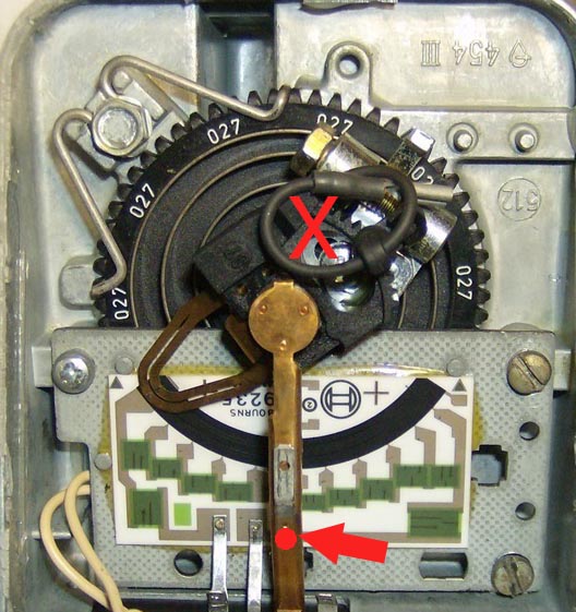
On the flow meters of BMW, and similar, you need to cut with a angle grinder(previously removed along with the connector) or side cutters current-carrying contact in the place indicated by the arrow and remove the slider from the axis.

On Digifant, Mazda and similar flow meters, remove the slider and unsolder the current-carrying wire. The current-carrying contact itself usually does not interfere.
Installing the magnet bushing
Install the bushing on the axle as far as it will go to the pinion. The bushing is usually loose and rotates – don’t pay attention to this for now.


Reviews
There are no reviews yet.